Understanding the Basics of Darlington Emitter Follower
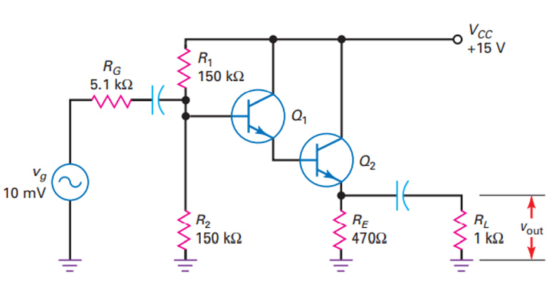 A Darlington emitter follower consists of two bipolar transistors connected in such a way that the emitter current of the first transistor drives the base of the second transistor. This clever arrangement creates a composite transistor with remarkably high current gain, typically the product of the individual transistors’ gains.
Key Components and Structure
- Two NPN or PNP transistors in cascade configuration
- Shared collector connection between both transistors
- First transistor’s emitter connected to second transistor’s base
- Optional bias resistors and protection diodes
Operating Principles
When a small input current is applied to the base of the first transistor, it gets amplified according to its gain (β1). The amplified current then flows into the base of the second transistor, where it gets amplified again by its gain (β2). The total current gain of the Darlington pair is approximately the product of the individual gains (β1 × β2).
| Parameter | Single Transistor | Darlington Pair |
|---|---|---|
| Current Gain (β) | 20-200 | 400-40,000 |
| Base-Emitter Voltage | 0.7V | 1.4V |
| Switching Speed | Fast | Slower |
| Input Impedance | Moderate | Very High |
Limitations and Disadvantages of Darlington Configuration
While the Darlington pair offers exceptional current gain, it’s important to understand its limitations for optimal circuit design. Here are the key challenges and their implications:
Major Drawbacks:
- Higher Base-Emitter Voltage Drop (VBE)
- Increased Saturation Voltage
- Slower Switching Speed
- Temperature Sensitivity
- Limited Bandwidth
Detailed Analysis of Limitations
| Limitation | Cause | Impact |
|---|---|---|
| Higher VBE (1.4V) | Cascaded Base-Emitter junctions | Increased power consumption, reduced efficiency |
| Increased VCE(sat) | Two transistors in series | Higher power dissipation in saturation |
| Slower Switching | Charge storage effects | Limited high-frequency performance |
| Temperature Effects | Compound thermal behavior | Requires careful thermal management |
Modern Solutions and Improvements
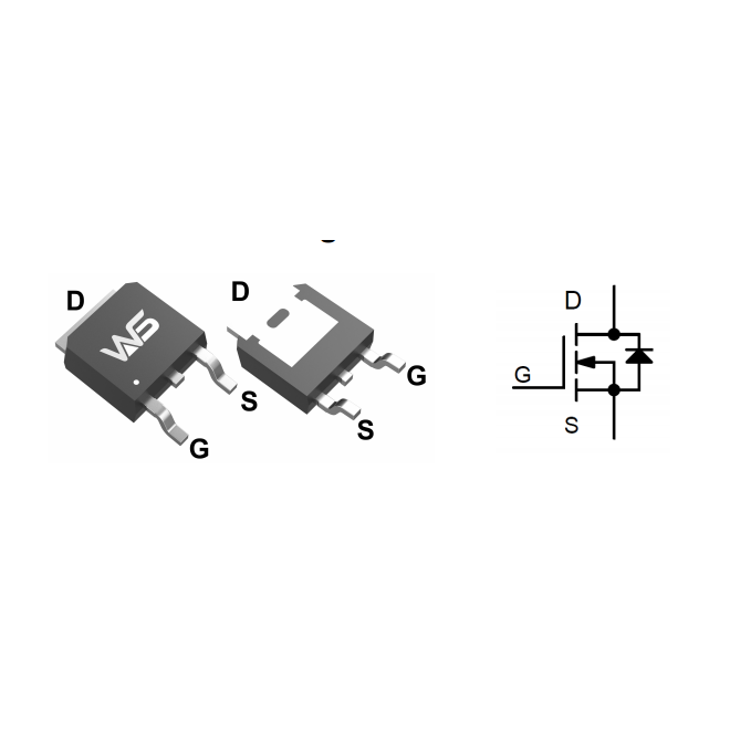
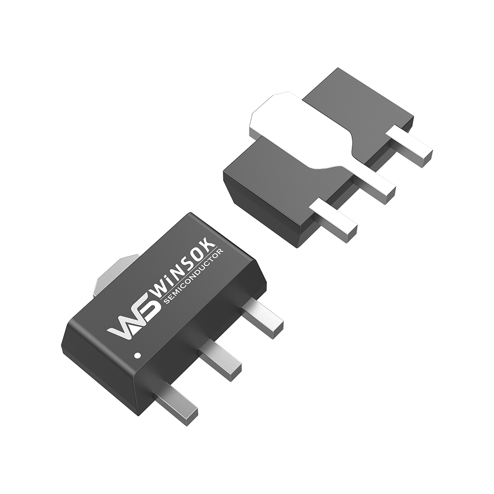
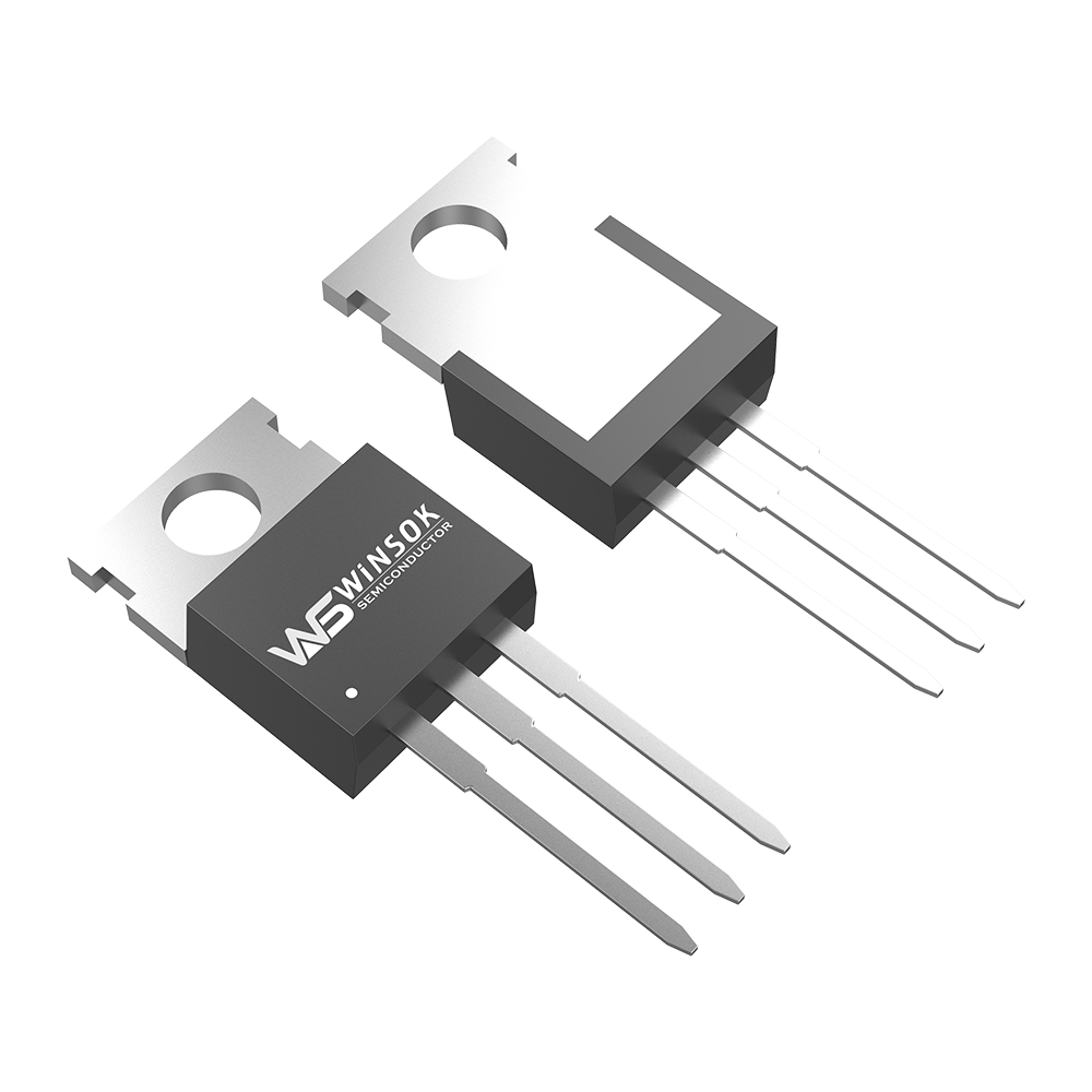
 At Olukey, we understand these challenges and offer advanced semiconductor solutions through our partnership with Winsok. Our modern MOSFET alternatives can address many of the traditional Darlington pair limitations while maintaining high performance.
Advanced Design Solutions
- Implementation of speed-up diodes for faster switching
- Integration of careful biasing networks
- Use of modern semiconductor materials
- Advanced thermal management techniques
Winsok’s Innovation in Power Electronics
Through our partnership with Winsok, we provide cutting-edge MOSFET solutions that offer:
- Lower power dissipation
- Faster switching speeds
- Better temperature stability
- Enhanced reliability and durability
Making the Right Choice for Your Application
Whether you’re designing power amplifiers, motor drivers, or high-current switching applications, choosing the right semiconductor configuration is crucial. While Darlington pairs remain valuable in specific applications, modern MOSFET solutions often provide superior performance.
Need expert guidance on selecting the best semiconductor solution for your application? Our team at Olukey, in partnership with Winsok, offers comprehensive technical support and product recommendations tailored to your specific needs.
Expert Support and Product Selection
As the authorized distributor for Winsok’s advanced MOSFET products, Olukey provides:
- Comprehensive technical support
- Custom solution design assistance
- Competitive pricing
- Reliable supply chain
- Quality assurance
Why Choose Olukey?
With our extensive experience in semiconductor distribution and deep partnership with Winsok, we offer:
- Direct access to factory support
- Latest product innovations
- Competitive lead times
- Professional technical consultation


