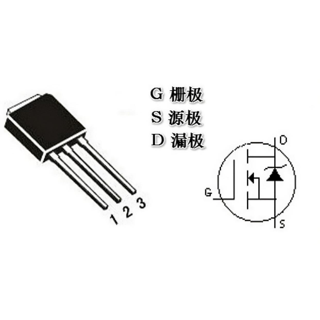
MOSFETs (Field Effect Tubes) usually have three pins, Gate (G for short), Source (S for short) and Drain (D for short). These three pins can be distinguished in the following ways:

I. Pin Identification
Gate (G):It is usually labelled "G" or can be identified by measuring the resistance to the other two pins, as the gate has a very high impedance in the unpowered state and is not significantly connected to the other two pins.
Source (S):Usually labelled "S" or "S2", it is the current inflow pin and is usually connected to the negative terminal of the MOSFET.
Drain (D):Usually labelled "D", it is the current flow pin and is connected to the positive terminal of the external circuit.
II. Pin Function
Gate (G):It is the key pin that controls the switching of the MOSFET, by controlling the voltage at the gate to control the on and off of the MOSFET. In the unpowered state, the impedance of the gate is generally very high, with no significant connection to the other two pins.
Source (S):is the current inflow pin and is usually connected to the negative terminal of the MOSFET. In NMOS, the source is usually grounded (GND); in PMOS, the source may be connected to a positive supply (VCC).
Drain (D):It is the current out pin and is connected to the positive terminal of the external circuit. In NMOS, the drain is connected to the positive supply (VCC) or load; in PMOS, the drain is connected to ground (GND) or load.
III. Measurement methods
Use a multimeter:
Set the multimeter to the appropriate resistance setting (e.g. R x 1k).
Use the negative terminal of the multimeter connected to any electrode, the other pen to contact the remaining two poles in turn, to measure its resistance.
If the two measured resistance values are approximately equal, the negative pen contact for the gate (G), because the gate and the other two pins between the resistance is usually very large.
Next, the multimeter will be dialled to R × 1 gear, the black pen connected to the source (S), the red pen connected to the drain (D), the measured resistance value should be a few ohms to dozens of ohms, indicating that the source and drain between the specific conditions can be conduction.
Observe the pin arrangement:
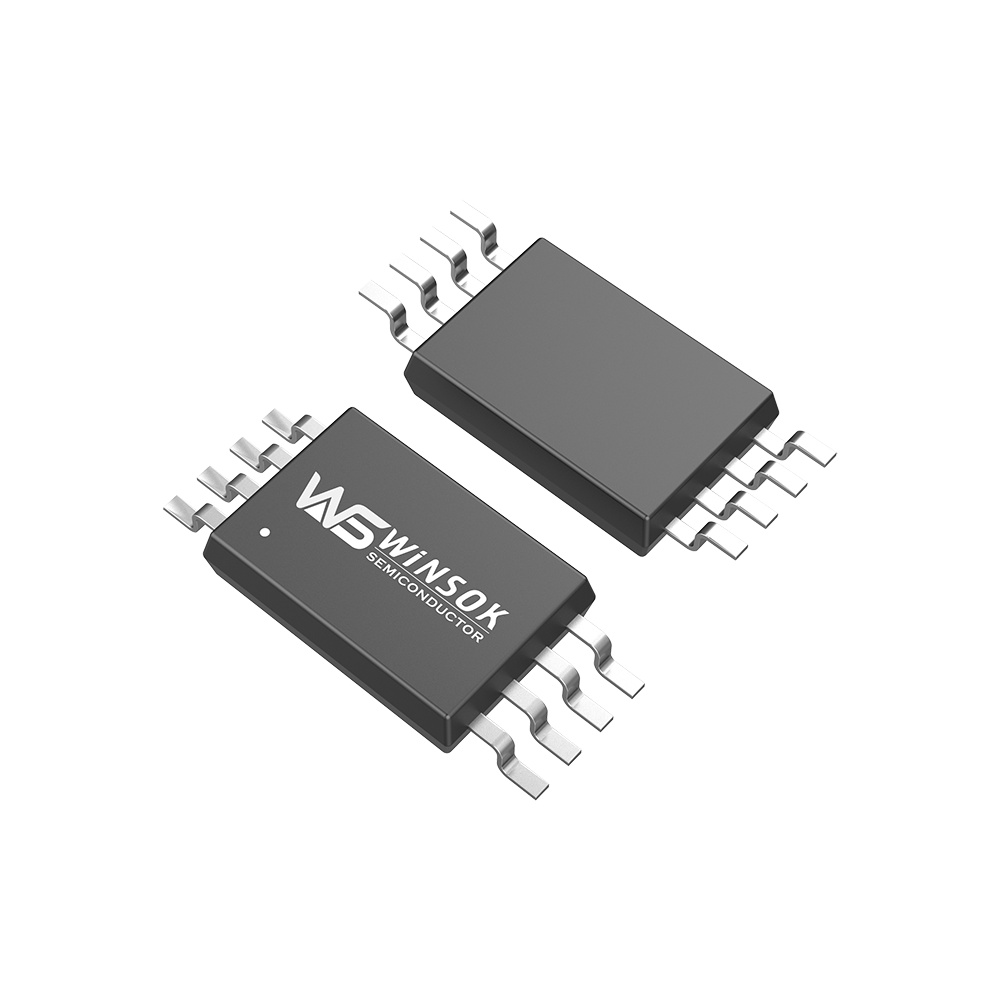
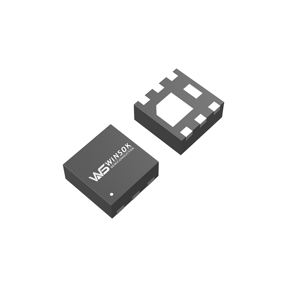
For MOSFETs with a well-defined pin arrangement (such as some package forms), the location and function of each pin can be determined by looking at the pin arrangement diagram or datasheet.
IV. Precautions
Different models of MOSFETs may have different pin arrangements and markings, so it is best to consult the datasheet or package drawing for the specific model before use.
When measuring and connecting the pins, be sure to pay attention to static electricity protection to avoid damaging the MOSFET.
MOSFETs are voltage-controlled devices with fast switching speeds, but in practical applications it is still necessary to pay attention to the design and optimisation of the drive circuit to ensure that the MOSFET can work properly and reliably.
In summary, the three pins of MOSFET can be accurately distinguished by various ways such as pin identification, pin function and measurement methods.


