Essential Knowledge
 Testing MOSFETs while they’re mounted on a circuit board requires careful attention to detail and the right approach to avoid damaging both the component and the surrounding circuitry. This guide provides comprehensive testing procedures and practical tips for in-circuit MOSFET diagnostics.
Required Testing Equipment
Primary Tools
- Digital multimeter (DMM)
- Oscilloscope
- Power supply
- Test probes
Optional Equipment
- Curve tracer
- Logic analyzer
- Thermal camera
Step-by-Step Testing Procedure
- Power down the circuit completely and wait for capacitors to discharge
- Identify the MOSFET pins (Gate, Drain, Source) on the board
- Set your multimeter to diode test mode
- Test Gate-to-Source junction
- Verify Drain-to-Source resistance
- Check for Gate oxide integrity
- Document all measurements for comparison
Common Testing Scenarios
| Symptom | Test Method | Expected Results |
|---|---|---|
| No switching action | Gate voltage measurement | Gate voltage should match driving signal |
| Overheating | RDS(on) measurement | Should match datasheet specifications |
| Intermittent operation | Thermal imaging scan | Uniform temperature distribution |
Pro Tip
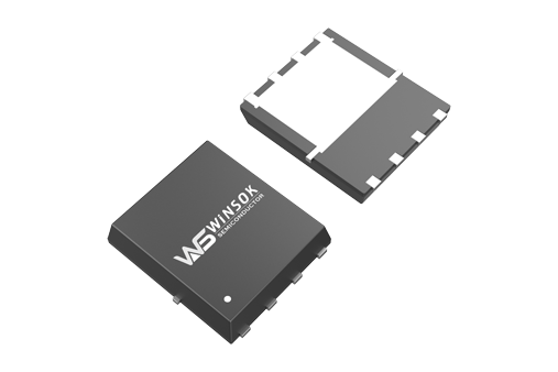
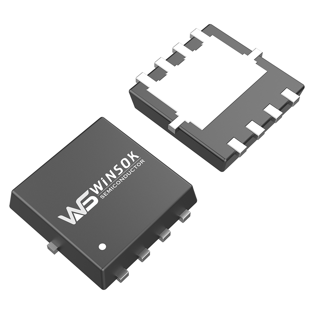
When testing surface-mount MOSFETs, use fine-tipped probes and consider using probe hooks for stable connections. This ensures accurate readings and prevents accidental shorts.
Advanced Testing Techniques
Dynamic Testing Methods
Beyond basic static measurements, dynamic testing can reveal issues that might not be apparent during simple multimeter tests:
- Switching time analysis using oscilloscope
- Gate charge measurement
- Thermal response under load
- Avalanche stress testing
Interpreting Test Results
| Measurement Point | Normal Range | Potential Issues |
|---|---|---|
| Gate-Source Resistance | Very high (MΩ range) | Low resistance indicates gate oxide damage |
| Drain-Source Resistance | Varies by model | Abnormally low/high suggests damage |
| Gate Threshold | 2-4V typical | Shift indicates degradation |
Common Pitfalls to Avoid
- Testing without proper ESD protection
- Ignoring parallel components’ influence
- Using incorrect probe polarity
- Failing to account for body diode effects
Troubleshooting Decision Tree
- Is the Gate-Source voltage reaching threshold?
- Yes → Check Drain current
- No → Verify gate drive circuit
- Is Drain-Source resistance normal?
- Yes → Check switching behavior
- No → MOSFET likely damaged
- Are switching transitions clean?
- Yes → Check thermal performance
- No → Investigate gate drive issues
Preventive Maintenance
Regular Testing Schedule
Implement these preventive maintenance procedures to ensure long-term reliability:
- Monthly visual inspection for signs of stress or damage
- Quarterly electrical parameter verification
- Semi-annual thermal imaging scan
- Annual complete system verification
Documentation and Reporting
Essential Records to Maintain
- Initial baseline measurements
- Periodic test results
- Environmental conditions during testing
- Observed anomalies and resolutions
- Component replacement history
Need Professional Testing Equipment?
Olukey provides complete testing solutions including professional-grade equipment and testing procedures. Contact our support team for customized testing solutions.


