
The Basic RDS(on) Formula
RDS(on) = VDS / ID (when the MOSFET is fully enhanced)
Where:
- VDS = Drain-to-Source Voltage
- ID = Drain Current
Factors Affecting RDS(on)
Temperature Dependency
RDS(on) typically increases with temperature, following the relationship:
RDS(on) at Tj = RDS(on) at 25°C × (1 + TC × ΔT)
Gate Voltage Impact
Higher gate voltage generally leads to lower RDS(on), until saturation is reached.
Device Construction
Depends on semiconductor material, chip size, and manufacturing process.
Practical Applications and Considerations
| Application | Typical RDS(on) Range | Key Considerations |
|---|---|---|
| Power Supplies | 1-10mΩ | Efficiency critical, heat management important |
| Motor Drivers | 5-50mΩ | Balance between cost and performance |
| Battery Management | 2-20mΩ | Low power loss required |
Featured Winsok MOSFETs from Olukey
As the authorized distributor of Winsok MOSFETs, we offer industry-leading solutions with optimized RDS(on) characteristics:

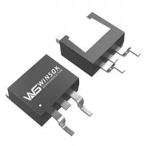
WSF3085 N-channel MOSFET
- Ultra-low RDS(on): 1.35mΩ typical
- 30V rating
- 85A continuous current
- TO-252-2L package
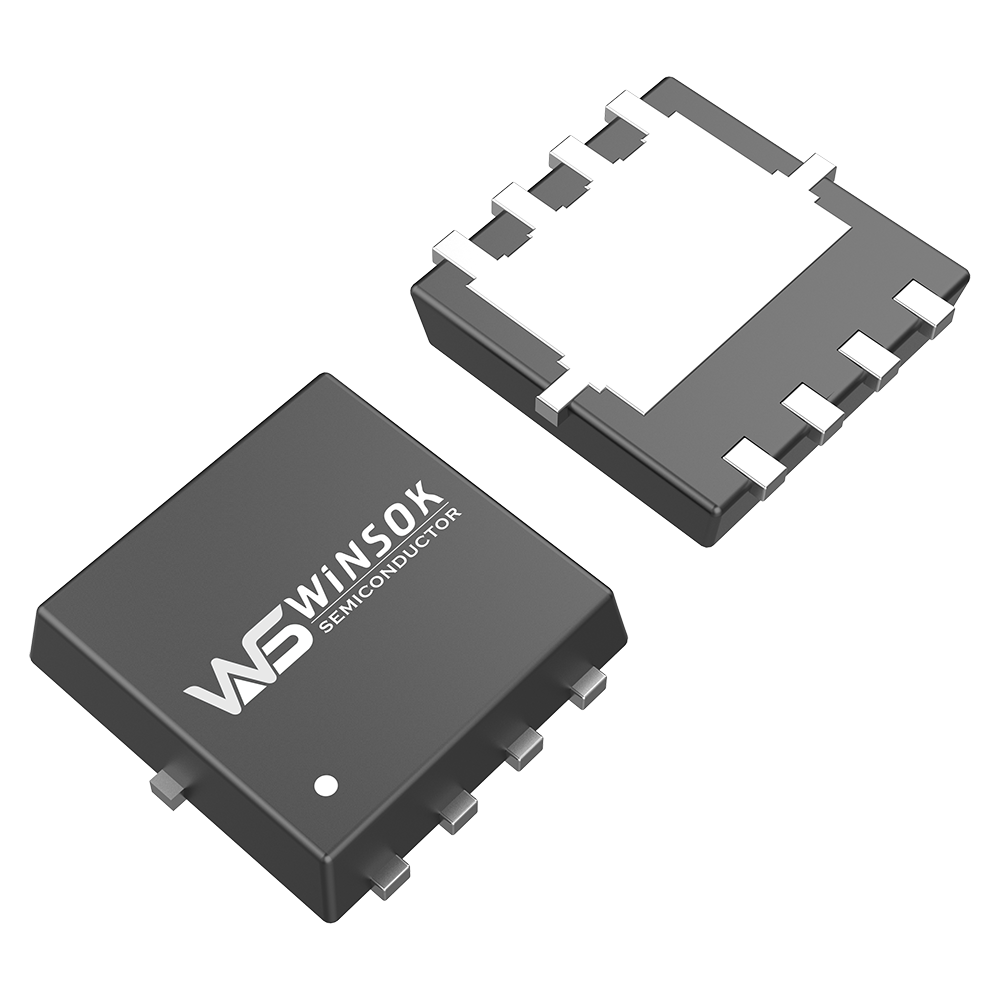
WSK220N04 N-channel MOSFET
- RDS(on): 1.2mΩ at VGS=10V
- 40V rating
- 220A continuous current
- TO-263-2L package
Advanced RDS(on) Calculations and Considerations
Total Power Loss Calculation
P(loss) = ID² × RDS(on) × D
Where:
- P(loss) = Power dissipated in watts
- ID = Drain current in amperes
- RDS(on) = On-state resistance in ohms
- D = Duty cycle (0 to 1)
Temperature Effects on RDS(on)
| Temperature (°C) | Typical RDS(on) Multiplier | Design Considerations |
|---|---|---|
| 25 | 1.0x | Reference temperature |
| 50 | 1.3x | Moderate derating needed |
| 75 | 1.6x | Significant derating required |
| 100 | 1.9x | Critical thermal management needed |
| 125 | 2.2x | Maximum recommended operation |
Design Optimization Strategies
Parallel Configuration
When MOSFETs are connected in parallel, the effective RDS(on) is calculated as:
RDS(on)_effective = RDS(on) / n
Where n is the number of parallel devices
Thermal Management
Calculate maximum junction temperature:
Tj = Ta + (P_loss × θja)
Where:
- Tj = Junction temperature
- Ta = Ambient temperature
- θja = Thermal resistance junction to ambient
Custom Solutions from Olukey
 As a leading semiconductor supplier, we offer:
- Comprehensive technical support and consultation
- Custom parameter matching for your specific application
- Extensive inventory for immediate delivery
- Competitive pricing and volume discounts
- Reliability testing and qualification support
Industry-Specific Applications
Automotive Electronics
- Battery management systems
- Motor control units
- LED lighting drivers
- DC-DC converters
Industrial Equipment
- Welding equipment
- Solar inverters
- UPS systems
- Industrial drives
Consumer Electronics
- Smartphone chargers
- Laptop adapters
- Home appliances
- Gaming consoles
Key Design Recommendations
- Always include a safety margin of at least 30% when calculating maximum current ratings
- Consider using parallel MOSFETs for high-current applications
- Implement proper thermal management solutions
- Account for temperature derating in worst-case scenarios
- Verify gate drive voltage is sufficient to achieve specified RDS(on)
 Ready to optimize your power electronic designs with industry-leading MOSFETs? Contact Olukey today for expert consultation and product selection support.


-

Flow of MOSFET testing
-

Understanding MOSFET: The Cornerstone of Modern...
-

What is TTL Logic: A Comprehensive Guide to Tra...
-

Understanding the function and structure of MOS...
-
What are the functions of MOSFET?
-
What is the role of small voltage MOSFETs?
-

The Difference Between a Body Diode and MOSFET
-

The Ultimate Guide to Electronic Component Data...
-

What Is JFET and MOSFET? Transistors that Power...
-

CMS32L051SS24 MCU Cmsemicon® Package SSOP24 Bat...
-

Take a look at MOSFETs
-
The three main roles of MOSFETs
-

MOSFET 101: The Ultimate Beginner’s Guide...
-

Do you know the definition of MOSFET?
-

CMS8H1213 MCU Cmsemicon® Package SSOP24 Batch 24+
-

What are the main features of MOSFETs?


