Operating Regions and Characteristics
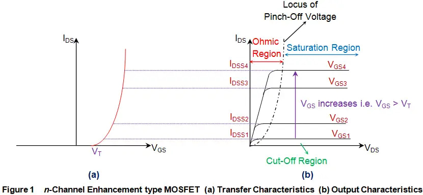
Cut-off Region
When VGS < Vth (threshold voltage)
Device acts as an open circuit
Linear/Triode Region
When VGS > Vth and VDS < (VGS – Vth)
Device behaves like a voltage-controlled resistor
Saturation Region
When VGS > Vth and VDS > (VGS – Vth)
Current remains relatively constant with VDS
Key V-I Characteristics Parameters
VGS(th)Gate threshold voltage
Typically 2-4V for power MOSFETs
RDS(on)On-state resistance
Key parameter for conduction losses
gmTransconductance
Indicates current control capability
BVDSSBreakdown voltage
Maximum VDS rating
Temperature Effects on V-I Characteristics
Temperature significantly influences MOSFET V-I characteristics:
VGS(th) Variation
Decreases with increasing temperature at approximately -2mV/°C to -6mV/°C
RDS(on) Change
Increases with temperature due to reduced carrier mobility
Transconductance
Decreases at higher temperatures, affecting switching performance
Understanding Output Characteristics
Output characteristics (ID vs VDS) demonstrate the MOSFET’s behavior at different gate voltages, crucial for:
• Load line analysis
• Operating point selection
• Power dissipation calculations
Key Regions in Output Characteristics
Active Region
Ideal for:
- Linear amplification
- Variable resistance applications
- Current sensing
Ohmic Region
Benefits include:
- Minimal voltage drop
- Lower power dissipation
- Switching applications
Transfer Characteristics Analysis
Transfer characteristics (ID vs VGS) are essential for understanding:
Switching Threshold
ID = 250µA × (W/L)
Linear Region Slope
Temperature Coefficient
Typically negative for VGS(th)
Safe Operating Area (SOA)
The SOA defines the voltage and current limits within which the MOSFET can safely operate. Key limiting factors include:
- Maximum drain current (ID(max))
- Maximum drain-source voltage (BVDSS)
- Maximum power dissipation (PD(max))
- Secondary breakdown limits
Selection Criteria Based on V-I Characteristics
Switching Applications
Focus on:
- Low RDS(on)
- Fast switching speed
- Gate charge characteristics
Linear Applications
Priority on:
- Transconductance linearity
- Temperature stability
- Safe operating area
Need Expert Guidance on MOSFET Selection?
Olukey offers Winsok’s comprehensive range of power MOSFETs with detailed V-I characteristics documentation and application support.
Technical Support and Resources
Documentation
- Detailed datasheets
- Application notes
- SPICE models
- Design guidelines
Engineering Support
- Parameter verification
- Application optimization
- Thermal analysis
- Reliability consultation


