


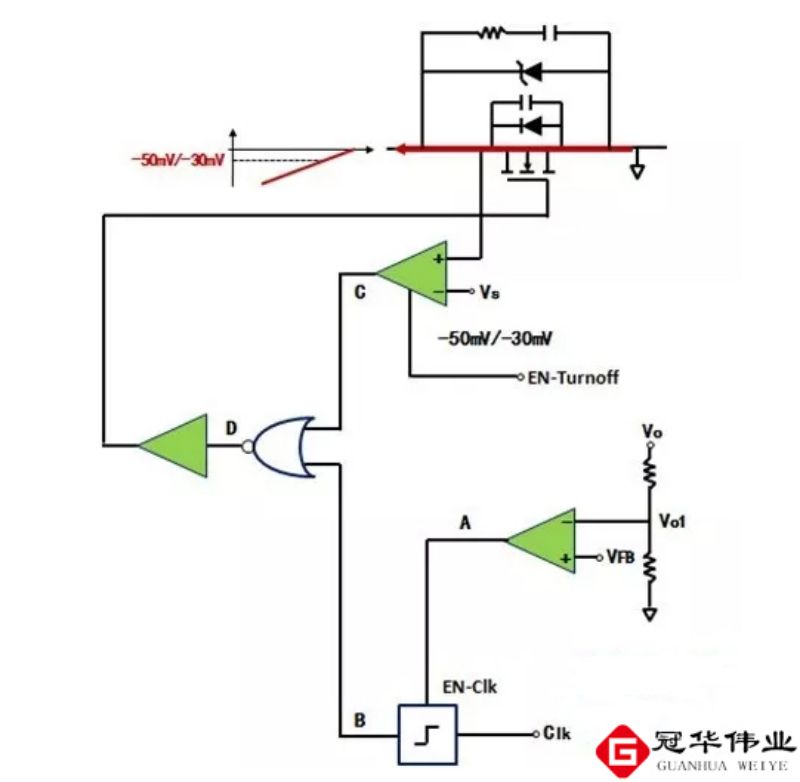
The four regions of an N-channel enhancement MOSFET
(1) Variable resistance region (also called unsaturated region)
Ucs" Ucs (th) (turn-on voltage), uDs" UGs-Ucs (th), is the region to the left of the preclamped trace in the figure where the channel is turned on. The value of UDs is small in this region, and the channel resistance is basically controlled only by UGs. When uGs is certain, ip and uDs into a linear relationship, the region is approximated as a set of straight lines. At this time, the field effect tube D, S between the equivalent of a voltage UGS
Controlled by the voltage UGS variable resistance.
(2) constant current region (also known as saturation region, amplification region, active region)
Ucs ≥ Ucs (h) and Ubs ≥ UcsUssth), for the figure of the right side of the pre-pinch off track, but not yet broken down in the region, in the region, when the uGs must be, ib almost does not change with the UDs, is a constant-current characteristics. i is controlled only by the UGs, then the MOSFETD, S is equivalent to a voltage uGs control of the current source. MOSFET is used in amplification circuits, generally on the work of the MOSFET D, S is equivalent to a voltage uGs control current source. MOSFET used in amplification circuits, generally work in the region, so also known as the amplification area.
(3) Clip-off area (also called cut-off area)
Clip-off area (also known as cut-off area) to meet the ucs "Ues (th) for the figure near the horizontal axis of the region, the channel is all clamped off, known as the full clip off, io = 0, the tube does not work.
(4) breakdown zone location
The breakdown region is located in the region on the right side of the figure. With the increasing UDs, the PN junction is subjected to too much reverse voltage and breakdown, ip increases sharply. The tube should be operated so as to avoid operating in the breakdown region. The transfer characteristic curve can be derived from the output characteristic curve. On the method used as a graph to find. For example, in Figure 3 (a) for Ubs = 6V vertical line, its intersection with the various curves corresponding to the i, Us values in the ib- Uss coordinates connected to the curve, that is, to obtain the transfer characteristic curve.
Parameters of MOSFET
There are many parameters of MOSFET, including DC parameters, AC parameters and limit parameters, but only the following main parameters need to be concerned in common use: saturated drain-source current IDSS pinch-off voltage Up, (junction-type tubes and depletion-type insulated-gate tubes, or turn-on voltage UT (reinforced insulated-gate tubes), trans-conductance gm, leakage-source breakdown voltage BUDS, maximum dissipated power PDSM, and maximum drain-source current IDSM .
(1) Saturated drain current
The saturated drain current IDSS is the drain current in a junction or depletion type insulated gate MOSFET when the gate voltage UGS = 0.
(2) Clip-off voltage
The pinch-off voltage UP is the gate voltage in a junction-type or depletion-type insulated-gate MOSFET that just cuts off between the drain and source. As shown in 4-25 for the N-channel tube UGS a ID curve, can be understood to see the significance of IDSS and UP
MOSFET four regions
(3) Turn-on voltage
The turn-on voltage UT is the gate voltage in a reinforced insulated-gate MOSFET that makes the inter-drain-source just conductive.
(4) Transconductance
The transconductance gm is the control ability of the gate source voltage UGS on the drain current ID, i.e., the ratio of the change in the drain current ID to the change in the gate source voltage UGS. 9m is an important parameter weighing the amplification ability of the MOSFET.
(5) Drain source breakdown voltage
Drain source breakdown voltage BUDS refers to the gate source voltage UGS certain, MOSFET normal operation can accept the maximum drain source voltage. This is a limit parameter, added to the MOSFET operating voltage must be less than BUDS.
(6) Maximum Power Dissipation
Maximum power dissipation PDSM is also a limit parameter, refers to the MOSFET performance does not deteriorate when the maximum permissible leakage source power dissipation. When using the MOSFET practical power consumption should be less than the PDSM and leave a certain margin.
(7) Maximum Drain Current
Maximum leakage current IDSM is another limit parameter, refers to the normal operation of the MOSFET, the leakage source of the maximum current allowed to pass through the MOSFET's operating current should not exceed the IDSM.
MOSFET Operating Principle
The operating principle of MOSFET (N-channel enhancement MOSFET) is to use VGS to control the amount of "inductive charge", in order to change the condition of the conductive channel formed by these "inductive charge", and then to achieve the purpose of controlling the drain current. The purpose is to control the drain current. In the manufacture of tubes, through the process of making a large number of positive ions in the insulating layer, so in the other side of the interface can be induced more negative charges, these negative charges can be induced.
When the gate voltage changes, the amount of charge induced in the channel also changes, the width of the conductive channel also changes, and thus the drain current ID changes with the gate voltage.
MOSFET role
I. MOSFET can be applied to amplification. Because of the high input impedance of the MOSFET amplifier, the coupling capacitor can be smaller capacity, without the use of electrolytic capacitors.
Second, the high input impedance of MOSFET is very suitable for impedance conversion. Commonly used in multi-stage amplifier input stage for impedance conversion.
MOSFET can be used as a variable resistor.
Fourth, MOSFET can be easily used as a constant current source.
Fifth, MOSFET can be used as an electronic switch.
-

Important Steps on MOSFET Selection
-

FET DFN2X2 package single P-channel 20V-40V mod...
-

Parameter analysis and measurement of MOSFETs
-

The relationship between MOSFET packaging and p...
-
Olukey: Let’s talk about the role of MOSFET in ...
-
Large Package MOSFET Design Knowledge
-

MOSFET gate source protection
-

The three pins of a MOSFET, how can I tell them...
-

MOSFET 101: The Ultimate Beginner’s Guide...
-
What parameters should I pay attention to when ...
-

Understanding the function and structure of MOS...
-

The Versatile 2N7000 Transistor: A Comprehensiv...
-

What is the difference between MOSFET and IGBT?...
-
MOSFETs in Electric Vehicle Controllers
-
Small Package MOSFETs
-

Flow of MOSFET testing


