
The basic power supply structure of fast charging QC uses flyback + secondary side (secondary) synchronous rectification SSR. For flyback converters, according to the feedback sampling method, it can be divided into: primary side (primary) regulation and secondary side (secondary) regulation; according to the location of the PWM controller. It can be divided into: primary side (primary) control and secondary side (secondary) control. It seems that it has nothing to do with MOSFET. So, Olukey has to ask: Where is the MOSFET hidden? What role did it play?
1. Primary side (primary) adjustment and secondary side (secondary) adjustment
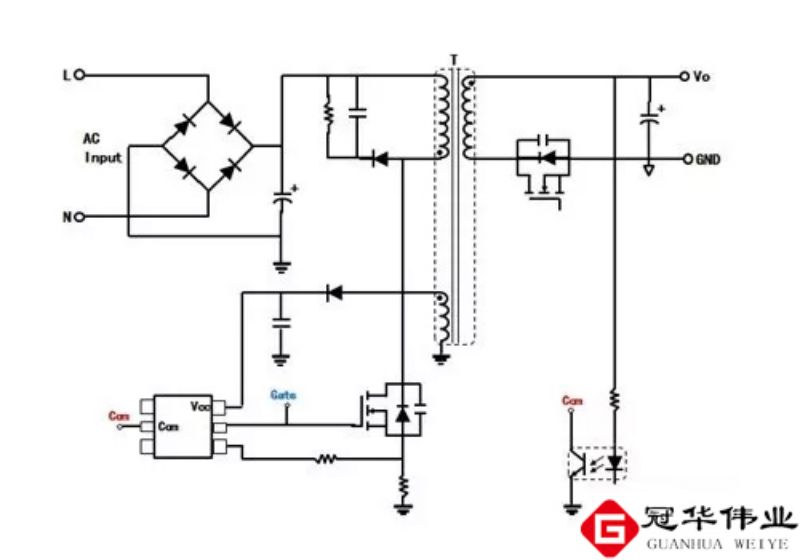
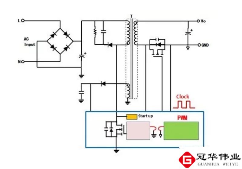
The stability of the output voltage requires a feedback link to send its changing information to the PWM main controller to adjust the changes in input voltage and output load. According to the different feedback sampling methods, it can be divided into primary side (primary) adjustment and secondary side (secondary) adjustment, as shown in Figures 1 and 2.
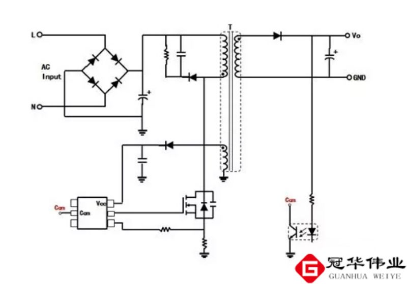
The feedback signal of primary side (primary) regulation is not taken directly from the output voltage, but from the auxiliary winding or the primary primary winding that maintains a certain proportional relationship with the output voltage. Its characteristics are:
① Indirect feedback method, poor load regulation rate and poor accuracy;
②. Simple and low cost;
③. No need for isolation optocoupler.
The feedback signal for secondary side (secondary) regulation is taken directly from the output voltage using an optocoupler and TL431. Its characteristics are:
① Direct feedback method, good load regulation rate, linear regulation rate, and high precision;
②. The adjustment circuit is complex and costly;
③. It is necessary to isolate the optocoupler, which has aging problems over time.
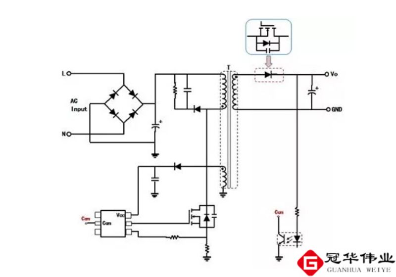
2. Secondary side (secondary) diode rectification and MOSFET synchronous rectification SSR
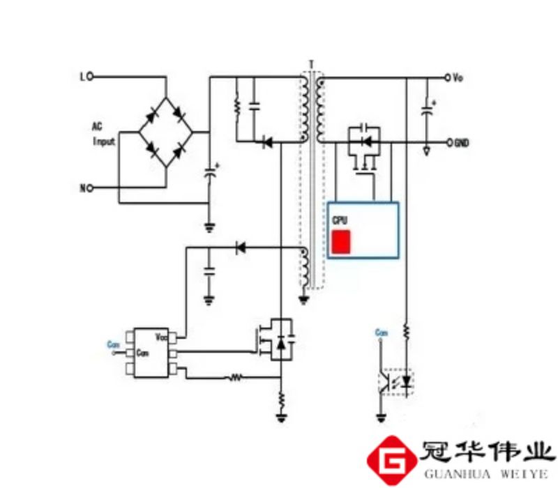
The secondary side (secondary) of the flyback converter usually uses diode rectification due to the large output current of fast charging. Especially for direct charging or flash charging, the output current is as high as 5A. In order to improve efficiency, MOSFET is used instead of the diode as the rectifier, which is called secondary (secondary) synchronous rectification SSR, as shown in Figures 3 and 4.
Characteristics of secondary side (secondary) diode rectification:
①. Simple, no additional drive controller is required, and the cost is low;
② When the output current is large, the efficiency is low;
③. High reliability.
Features of secondary side (secondary) MOSFET synchronous rectification:
①. Complex, requiring additional drive controller and high cost;
②. When the output current is large, the efficiency is high;
③. Compared with diodes, their reliability is low.
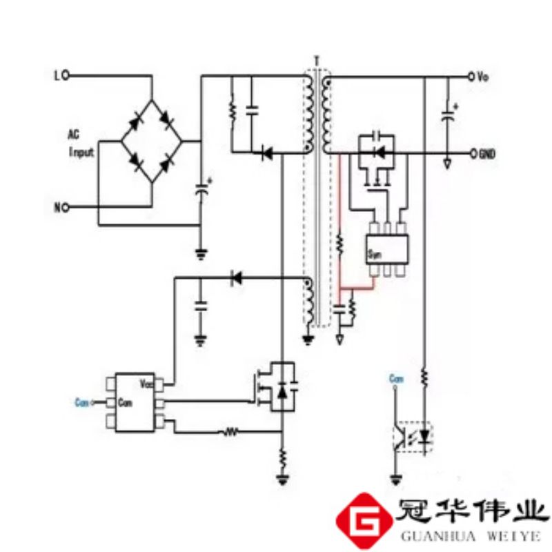
In practical applications, the MOSFET of the synchronous rectification SSR is usually moved from the high end to the low end to facilitate driving, as shown in Figure 5.
The characteristics of the high-end MOSFET of synchronous rectification SSR:
①. It requires bootstrap drive or floating drive, which is costly;
②. Good EMI.
The characteristics of synchronous rectification SSR MOSFET placed at the low end:
① Direct drive, simple drive and low cost;
②. Poor EMI.
3. Primary side (primary) control and secondary side (secondary) control
The PWM main controller is placed on the primary side (primary). This structure is called primary side (primary) control. In order to improve the accuracy of the output voltage, load regulation rate, and linear regulation rate, the primary side (primary) control requires an external optocoupler and TL431 to form a feedback link. The system bandwidth is small and the response speed is slow.
If the PWM main controller is placed on the secondary side (secondary), the optocoupler and TL431 can be removed, and the output voltage can be directly controlled and adjusted with fast response. This structure is called secondary (secondary) control.
Features of primary side (primary) control:
①. Optocoupler and TL431 are required, and the response speed is slow;
②. The speed of output protection is slow.
③. In synchronous rectification continuous mode CCM, the secondary side (secondary) requires a synchronization signal.
Features of secondary (secondary) control:
①. The output is directly detected, no optocoupler and TL431 are needed, the response speed is fast, and the output protection speed is fast;
②. The secondary side (secondary) synchronous rectification MOSFET is directly driven without the need for synchronization signals; additional devices such as pulse transformers, magnetic couplings or capacitive couplers are required to transmit the driving signals of the primary side (primary) high-voltage MOSFET.
③. The primary side (primary) needs a starting circuit, or the secondary side (secondary) has an auxiliary power supply for starting.
4. Continuous CCM mode or discontinuous DCM mode
The flyback converter can operate in continuous CCM mode or discontinuous DCM mode. If the current in the secondary (secondary) winding reaches 0 at the end of a switching cycle, it is called discontinuous DCM mode. If the current of the secondary (secondary) winding is not 0 at the end of a switching cycle, it is called continuous CCM mode, as shown in Figures 8 and 9.
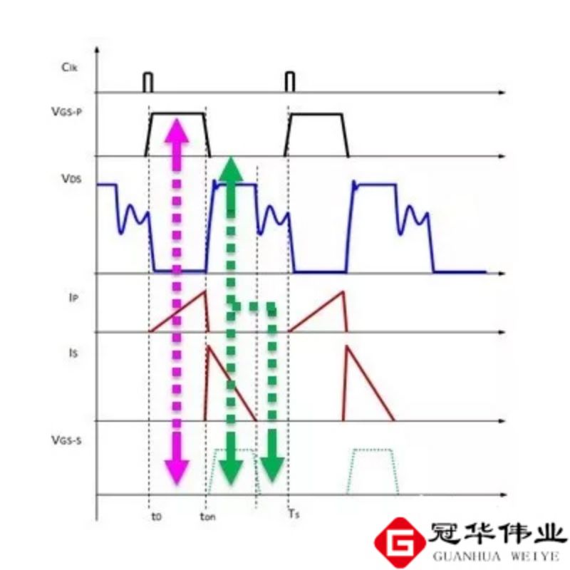
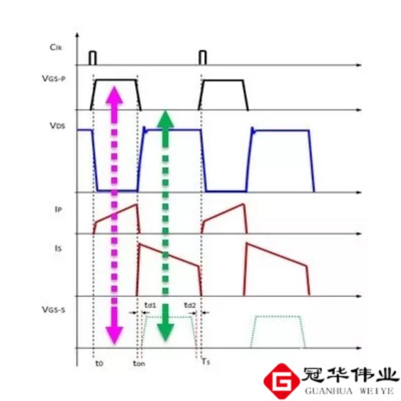
It can be seen from Figure 8 and Figure 9 that the working states of the synchronous rectification SSR are different in different operating modes of the flyback converter, which also means that the control methods of the synchronous rectification SSR will also be different.
If the dead time is ignored, when working in continuous CCM mode, the synchronous rectification SSR has two states:
①. The primary side (primary) high-voltage MOSFET is turned on, and the secondary side (secondary) synchronous rectification MOSFET is turned off;
②. The primary side (primary) high-voltage MOSFET is turned off, and the secondary side (secondary) synchronous rectification MOSFET is turned on.
Similarly, if the dead time is ignored, the synchronous rectification SSR has three states when operating in discontinuous DCM mode:
①. The primary side (primary) high-voltage MOSFET is turned on, and the secondary side (secondary) synchronous rectification MOSFET is turned off;
②. The primary side (primary) high-voltage MOSFET is turned off, and the secondary side (secondary) synchronous rectification MOSFET is turned on;
③. The primary side (primary) high-voltage MOSFET is turned off, and the secondary side (secondary) synchronous rectification MOSFET is turned off.
5. Secondary side (secondary) synchronous rectification SSR in continuous CCM mode
If the fast-charge flyback converter operates in the continuous CCM mode, the primary side (primary) control method, the secondary side (secondary) synchronous rectification MOSFET requires a synchronization signal from the primary side (primary) to control the shutdown.
The following two methods are usually used to obtain the synchronous drive signal of the secondary side (secondary):
(1) Directly use the secondary (secondary) winding, as shown in Figure 10;
(2) Use additional isolation components such as pulse transformers to transmit the synchronous drive signal from the primary side (primary) to the secondary side (secondary), as shown in Figure 12.
Directly using the secondary (secondary) winding to obtain the synchronous drive signal, the accuracy of the synchronous drive signal is very difficult to control, and it is difficult to achieve optimized efficiency and reliability. Some companies even use digital controllers to improve control accuracy, as shown in Figure 11 Show.
Using a pulse transformer to obtain synchronous driving signals has high accuracy, but the cost is relatively high.
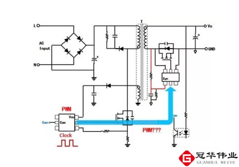
The secondary side (secondary) control method usually uses a pulse transformer or magnetic coupling method to transmit the synchronous drive signal from the secondary side (secondary) to the primary side (primary), as shown in Figure 7.v
6. Secondary side (secondary) synchronous rectification SSR in discontinuous DCM mode
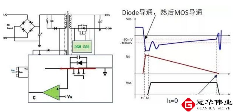
If the fast charge flyback converter operates in discontinuous DCM mode. Regardless of the primary side (primary) control method or the secondary side (secondary) control method, the D and S voltage drops of the synchronous rectification MOSFET can be directly detected and controlled.
(1) Turning on the synchronous rectification MOSFET
When the voltage of VDS of the synchronous rectification MOSFET changes from positive to negative, the internal parasitic diode turns on, and after a certain delay, the synchronous rectification MOSFET turns on, as shown in Figure 13.
(2) Turning off the synchronous rectification MOSFET
After the synchronous rectification MOSFET is turned on, VDS=-Io*Rdson. When the secondary (secondary) winding current decreases to 0, that is, when the voltage of the current detection signal VDS changes from negative to 0, the synchronous rectification MOSFET turns off, as shown in Figure 13.
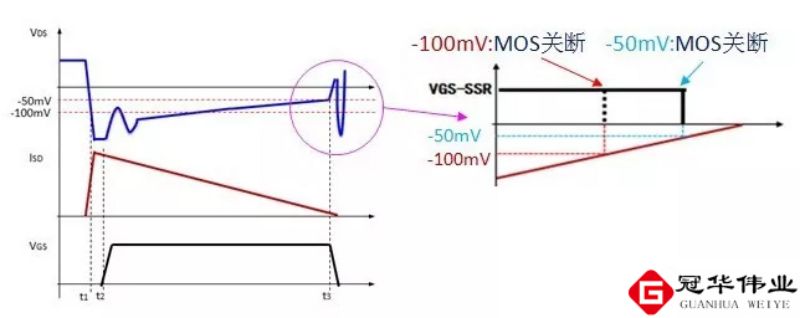
In practical applications, the synchronous rectification MOSFET turns off before the secondary (secondary) winding current reaches 0 (VDS=0). The current detection reference voltage values set by different chips are different, such as -20mV, -50mV, -100mV, -200mV, etc.
The current detection reference voltage of the system is fixed. The greater the absolute value of the current detection reference voltage, the smaller the interference error and the better the accuracy. However, when the output load current Io decreases, the synchronous rectification MOSFET will turn off at a larger output current, and its internal parasitic diode will conduct for a longer time, so the efficiency is reduced, as shown in Figure 14.
In addition, if the absolute value of the current detection reference voltage is too small. System errors and interference may cause the synchronous rectification MOSFET to turn off after the secondary (secondary) winding current exceeds 0, resulting in reverse inflow current, affecting efficiency and system reliability.
High-precision current detection signals can improve the efficiency and reliability of the system, but the cost of the device will increase. The accuracy of the current detection signal is related to the following factors:
①. Accuracy and temperature drift of current detection reference voltage;
②. The bias voltage and offset voltage, bias current and offset current, and temperature drift of the current amplifier;
③. The accuracy and temperature drift of the on-voltage Rdson of the synchronous rectification MOSFET.
In addition, from a system perspective, it can be improved through digital control, changing current detection reference voltage, and changing synchronous rectification MOSFET driving voltage.
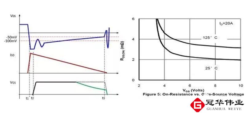
When the output load current Io decreases, if the driving voltage of the power MOSFET decreases, the corresponding MOSFET turn-on voltage Rdson increases. As shown in Figure 15, it is possible to avoid early shutdown of the synchronous rectification MOSFET, reduce the conduction time of the parasitic diode, and improve the efficiency of the system.
It can be seen from Figure 14 that when the output load current Io decreases, the current detection reference voltage also decreases. In this way, when the output current Io is large, a higher current detection reference voltage is used to improve the control accuracy; when the output current Io is low, a lower current detection reference voltage is used. It can also improve the conduction time of the synchronous rectification MOSFET and improve the efficiency of the system.
When the above method cannot be used for improvement, Schottky diodes can also be connected in parallel at both ends of the synchronous rectification MOSFET. After the synchronous rectification MOSFET is turned off in advance, an external Schottky diode can be connected for freewheeling.
7. Secondary (secondary) control CCM+DCM hybrid mode
Currently, there are basically two commonly used solutions for mobile phone fast charging:
(1) Primary side (primary) control and DCM working mode. Secondary side (secondary) synchronous rectification MOSFET does not require a synchronization signal.
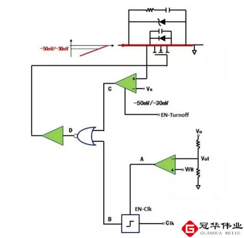
(2) Secondary (secondary) control, CCM+DCM mixed operating mode (when the output load current decreases, from CCM to DCM). The secondary side (secondary) synchronous rectification MOSFET is directly driven, and its turn-on and turn-off logic principles are shown in Figure 16:
Turning on the synchronous rectification MOSFET: When the voltage of VDS of the synchronous rectification MOSFET changes from positive to negative, its internal parasitic diode turns on. After a certain delay, the synchronous rectification MOSFET turns on.
Turning off the synchronous rectification MOSFET:
① When the output voltage is less than the set value, the synchronous clock signal is used to control the turn-off of the MOSFET and work in CCM mode.
② When the output voltage is greater than the set value, the synchronous clock signal is shielded and the working method is the same as the DCM mode. The VDS=-Io*Rdson signal controls the shutdown of the synchronous rectification MOSFET.
Now, everyone knows what role MOSFET plays in the entire fast charging QC!
About Olukey
Olukey's core team has focused on components for 20 years and is headquartered in Shenzhen. Main business: MOSFET, MCU, IGBT and other devices. The main agent products are WINSOK and Cmsemicon. Products are widely used in military industry, industrial control, new energy, medical products, 5G, Internet of Things, smart homes, and various consumer electronics products. Relying on the advantages of the original global general agent, we are based on the Chinese market. We use our comprehensive advantageous services to introduce various advanced high-tech electronic components to our customers, assist manufacturers in producing high-quality products and provide comprehensive services.


-

The connection between MOSFETs and Field Effect...
-

MOSFET Solid State Relays: Revolutionizing Mode...
-

Understanding CMOS Switch Technology: From Basi...
-

PCM3360Q High-performance electronic components...
-

Understanding the Operation and Modeling of MOS...
-

Complete Guide to Optocoupler MOSFET Driver Cir...
-

MOSFET Solid State Relay Circuits: Revolutionar...
-
How do MOSFETs work?
-

Do you know the MOSFET driver circuit?
-

RDS(on) in MOSFETs: The Critical Parameter for ...
-

Fast Switching MOSFET Circuits: Revolutionary P...
-

How to Use a MOSFET: Complete Guide for Beginne...
-
MOSFET small current heating causes and measures
-
How to correctly select small voltage MOSFETs
-
Commonly used SMD MOSFET package pinout sequenc...
-

How can I tell the difference between a Mosfets...


