
Specific plan: a high-power MOSFET heat dissipation device, including a hollow structure casing and a circuit board. The circuit board is arranged in the casing. A number of side-by-side MOSFETs are connected to both ends of the circuit board through pins. It also includes a device for compressing the MOSFETs. The MOSFET is made to be close to the heat dissipation pressure block on the inner wall of the casing. The heat dissipation pressure block has a first circulating water channel running through it. The first circulating water channel is vertically arranged with a plurality of side-by-side MOSFETs. The side wall of the housing is provided with a second circulating water channel parallel to the first circulating water channel, and the second circulating water channel is close to the corresponding MOSFET. The heat dissipation pressure block is provided with several threaded holes. The heat dissipation pressure block is fixedly connected to the inner wall of the casing through screws. The screws are screwed into the threaded holes of the heat dissipation pressure block from the threaded holes on the side wall of the casing. The outer wall of the casing is provided with a heat dissipation groove. Support bars are provided on both sides of the inner wall of the housing to support the circuit board. When the heat dissipation pressure block is fixedly connected to the inner wall of the housing, the circuit board is pressed between the side walls of the heat dissipation pressure block and the support bars. There is an insulating film between the MOSFET and the inner wall of the casing, and there is an insulating film between the heat dissipation pressure block and the MOSFET. The side wall of the shell is provided with a heat dissipation pipe perpendicular to the first circulating water channel. One end of the heat dissipation pipe is provided with a radiator, and the other end is closed. The radiator and the heat dissipation pipe form a closed inner cavity, and the inner cavity is provided with refrigerant. The heat sink includes a heat dissipation ring fixedly connected to the heat dissipation pipe and a heat dissipation fin fixedly connected to the heat dissipation ring; the heat sink is also fixedly connected to a cooling fan.
Specific effects: Increase the heat dissipation efficiency of MOSFET and improve the service life of MOSFET; improve the heat dissipation effect of the casing, keeping the temperature inside the casing stable; simple structure and easy installation.
The above description is only an overview of the technical solution of the present invention. In order to understand the technical means of the present invention more clearly, it can be implemented according to the contents of the description. In order to make the above and other objects, features and advantages of the present invention more obvious and understandable, preferred embodiments are described in detail below along with the accompanying drawings.
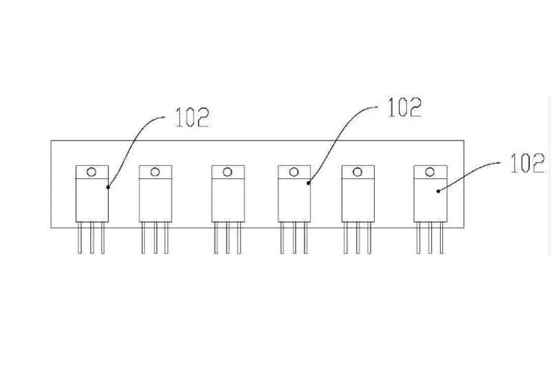
The heat dissipation device includes a hollow structure casing 100 and a circuit board 101. The circuit board 101 is arranged in the casing 100. A number of side-by-side MOSFETs 102 are connected to both ends of the circuit board 101 through pins. It also includes a heat dissipation pressure block 103 for compressing the MOSFET 102 so that the MOSFET 102 is close to the inner wall of the housing 100. The heat dissipation pressure block 103 has a first circulating water channel 104 running through it. The first circulating water channel 104 is vertically arranged with several side-by-side MOSFETs 102.
The heat dissipation pressure block 103 presses the MOSFET 102 against the inner wall of the housing 100, and part of the heat of the MOSFET 102 is conducted to the housing 100. Another part of the heat is conducted to the heat dissipation block 103, and the housing 100 dissipates the heat to the air. The heat of the heat dissipation block 103 is taken away by the cooling water in the first circulating water channel 104, which improves the heat dissipation effect of the MOSFET 102. At the same time, part of the heat generated by other components in the housing 100 is also conducted to the heat dissipation pressure block 103. Therefore, the heat dissipation pressure block 103 can further reduce the temperature in the housing 100 and improve the working efficiency and service life of other components in the housing 100; The casing 100 has a hollow structure, so heat is not easily accumulated in the casing 100 , thus preventing the circuit board 101 from overheating and burning out. The side wall of the housing 100 is provided with a second circulating water channel 105 parallel to the first circulating water channel 104 , and the second circulating water channel 105 is close to the corresponding MOSFET 102 . The outer wall of the housing 100 is provided with a heat dissipation groove 108 . The heat of the housing 100 is mainly taken away through the cooling water in the second circulating water channel 105 . Another part of the heat is dissipated through the heat dissipation groove 108, which improves the heat dissipation effect of the housing 100. The heat dissipation pressure block 103 is provided with several threaded holes 107. The heat dissipation pressure block 103 is fixedly connected to the inner wall of the housing 100 through screws. The screws are screwed into the threaded holes of the heat dissipation pressure block 103 from the threaded holes on the side walls of the housing 100.
In the present invention, a connecting piece 109 extends from the edge of the heat dissipation pressure block 103. The connecting piece 109 is provided with a number of threaded holes 107. The connecting piece 109 is fixedly connected to the inner wall of the housing 100 through screws. Support bars 106 are provided on both sides of the inner wall of the housing 100 to support the circuit board 101. When the heat dissipation pressure block 103 is fixedly connected to the inner wall of the housing 100, the circuit board 101 is pressed between the side walls of the heat dissipation pressure block 103 and the support bars 106. During installation, the circuit board 101 is first placed on the surface of the support bar 106, and the bottom of the heat dissipation pressure block 103 is pressed against the upper surface of the circuit board 101. Then, the heat dissipation pressure block 103 is fixed to the inner wall of the housing 100 with screws. A clamping groove is formed between the heat dissipation pressure block 103 and the support bar 106 to clamp the circuit board 101 to facilitate the installation and removal of the circuit board 101. At the same time, the circuit board 101 is close to the heat dissipation pressure block 103 . Therefore, the heat generated by the circuit board 101 is conducted to the heat dissipation pressure block 103, and the heat dissipation pressure block 103 is carried away by the cooling water in the first circulating water channel 104, thus preventing the circuit board 101 from overheating and burning. Preferably, an insulating film is disposed between the MOSFET 102 and the inner wall of the housing 100 , and an insulating film is disposed between the heat dissipation pressure block 103 and the MOSFET 102 .
A high-power MOSFET heat dissipation device includes a hollow structure casing 200 and a circuit board 202. The circuit board 202 is arranged in the casing 200. A number of side-by-side MOSFETs 202 are respectively connected to both ends of the circuit board 202 through pins, and also includes a heat dissipation pressure block 203 for compressing the MOSFETs 202 so that the MOSFETs 202 are close to the inner wall of the housing 200 . A first circulating water channel 204 runs through the heat dissipation pressure block 203. The first circulating water channel 204 is vertically arranged with several side-by-side MOSFETs 202. The side wall of the shell is provided with a heat dissipation pipe 205 perpendicular to the first circulating water channel 204, and one end of the heat dissipation pipe 205 is provided with a heat dissipation body 206. The other end is closed, and the heat dissipation body 206 and the heat dissipation pipe 205 form a closed inner cavity, and refrigerant is arranged in the inner cavity. MOSFET 202 generates heat and vaporizes the refrigerant. When vaporizing, it absorbs the heat from the heating end (close to the MOSFET 202 end), and then flows from the heating end to the cooling end (away from the MOSFET 202 end). When it encounters cold at the cooling end, it releases heat to the outer periphery of the tube wall. The liquid then flows to the heating end, thus forming a heat dissipation circuit. This heat dissipation through vaporization and liquid is much better than the heat dissipation of conventional heat conductors. The heat dissipation body 206 includes a heat dissipation ring 207 fixedly connected to the heat dissipation pipe 205 and a heat dissipation fin 208 fixedly connected to the heat dissipation ring 207; the heat dissipation fin 208 is also fixedly connected to a cooling fan 209.
The heat dissipation ring 207 and the heat dissipation pipe 205 have a long fitting distance, so that the heat dissipation ring 207 can quickly transfer the heat in the heat dissipation pipe 205 to the heat sink 208 to achieve rapid heat dissipation.


-

What Is a Switched Mode Power Supply?
-

About MOSFET package type
-

What Is MCU in Electronics: The Brain Behind Sm...
-

What is TTL Logic: A Comprehensive Guide to Tra...
-
What are the causes of inverter MOSFET heating?
-

MOSFET vs FET: Why Modern Electronics Choose Me...
-

Do you know about depletion MOSFETs?
-

Market Leaders: The Most Popular MOSFETs Drivin...
-

Power MOSFET Package Types Guide
-

What do the three pins G, S, and D of the packa...
-

Understanding Cascode Amplifier MOSFETs: The Ul...
-
What is the principle of operation of MOSFET?
-
How to correctly select small voltage MOSFETs
-
How to choose MOSFET?
-

What is the difference between MOSFET and IGBT?...
-

Understanding MOSFET Switching Characteristics ...


