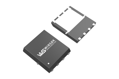
D-FET is in the 0 gate bias when the existence of channel, can conduct the FET; E-FET is in the 0 gate bias when there is no channel, can not conduct the FET. these two types of FETs have their own characteristics and uses. In general, enhanced FET in high-speed, low-power circuits is very valuable; and this device is working, it is the polarity of the gate bias voltage and drain voltage of the same, it is more convenient in circuit design.
The so-called enhanced means: when VGS = 0 tube is a cut-off state, plus the correct VGS, the majority of carriers are attracted to the gate, thus "enhancing" the carriers in the region, forming a conductive channel. n-channel enhanced MOSFET is basically a left-right symmetrical topology, which is the P-type semiconductor on the generation of a layer of SiO2 film insulation. It generates an insulating layer of SiO2 film on the P-type semiconductor, and then diffuses two highly doped N-type regions by photolithography, and leads electrodes from the N-type region, one for the drain D and one for the source S. A layer of aluminum metal is plated on the insulating layer between the source and the drain as the gate G. When VGS = 0 V, there are quite a few diodes with back-to-back diodes between the drain and the source and the voltage between D and S does not form a current between D and S. The current between D and S is not formed by the voltage applied.
When the gate voltage is added, if 0 < VGS < VGS(th), through the capacitive electric field formed between the gate and the substrate, the polyon holes in the P-type semiconductor near the bottom of the gate are repelled downward, and a thin depletion layer of negative ions appears; at the same time, it will attract the oligons therein to move to the surface layer, but the number is limited and insufficient to form a conductive channel that communicates the drain and source, so it is still insufficient to Formation of drain current ID. further increase VGS, when VGS > VGS (th) (VGS (th) is called the turn-on voltage), because at this time the gate voltage has been relatively strong, in the P-type semiconductor surface layer near the bottom of the gate below the gathering of more electrons, you can form a trench, the drain and the source of communication. If the drain source voltage is added at this time, the drain current can be formed ID. electrons in the conductive channel formed below the gate, because of the carrier hole with the P-type semiconductor polarity is opposite, so it is called anti-type layer. As VGS continues to increase, ID will continue to increase. ID = 0 at VGS = 0V, and the drain current occurs only after VGS > VGS(th), so, this type of MOSFET is called enhancement MOSFET.
The control relationship of VGS on drain current can be described by the curve iD = f(VGS(th))|VDS=const, which is called the transfer characteristic curve, and the magnitude of the slope of the transfer characteristic curve, gm, reflects the control of drain current by the gate source voltage. the magnitude of gm is mA/V, so gm is also called the transconductance.


