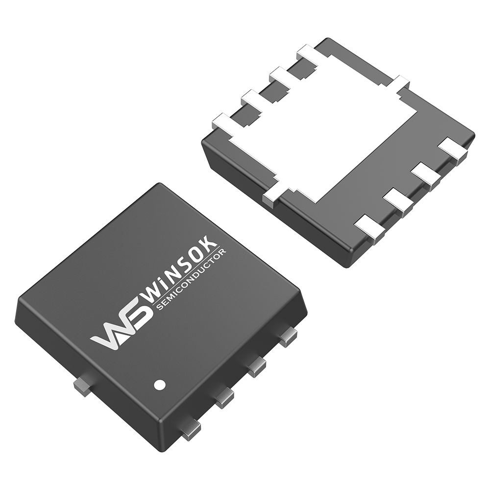
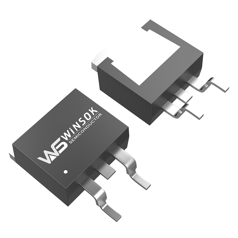
N type, P type MOSFET working principle of the essence is the same, MOSFET is mainly added to the input side of the gate voltage to successfully control the output side of the drain current, MOSFET is a voltage-controlled device, through the voltage added to the gate to control the characteristics of the device, unlike the triode to do switching time due to the base current caused by the charge storage effect, in switching applications, MOSFET's In switching applications, MOSFET's switching speed is faster than that of triode.
In the switching power supply, commonly used MOSFET open drain circuit, the drain is connected to the load as is, called open drain, open drain circuit, the load is connected to how high the voltage, are able to turn on, turn off the load current, is the ideal analog switching device, which is the principle of the MOSFET to do switching devices, the MOSFET to do switching in the form of more circuits.
In terms of switching power supply applications, this application requires MOSFETs to periodically conduct, turn off, such as DC-DC power supply commonly used in the basic buck converter relies on two MOSFETs to perform the switching function, these switches alternately in the inductor to store energy, release the energy to the load, often choose hundreds of kHz or even more than 1 MHz, mainly because the higher the frequency then, the smaller the magnetic components. During normal operation, the MOSFET is equivalent to a conductor, for example, high-power MOSFETs, small-voltage MOSFETs, circuits, power supply is the minimum conduction loss of the MOS.
MOSFET PDF parameters, MOSFET manufacturers have successfully adopted the RDS (ON) parameter to define the on-state impedance, for switching applications, RDS (ON) is the most important device characteristic; datasheets define RDS (ON), the gate (or drive) voltage VGS and current flowing through the switch is related, for adequate gate drive, RDS (ON) is a relatively static parameter; MOSFETs that have been in conduction are prone to heat generation, and slowly increasing junction temperatures can lead to an increase in RDS (ON); MOSFET datasheets specify the thermal impedance parameter, which is defined as the ability of the semiconductor junction of the MOSFET package to dissipate heat, and RθJC is simply defined as the junction-to-case thermal impedance.
1, the frequency is too high, sometimes over-pursuing the volume, will directly lead to high frequency, MOSFET on the loss increases, the greater the heat, do not do a good job of adequate heat dissipation design, high current, the nominal current value of the MOSFET, the need for good heat dissipation to be able to achieve; ID is less than the maximum current, may be serious heat, the need for adequate auxiliary heatsinks.
2, MOSFET selection errors and errors in power judgment, MOSFET internal resistance is not fully considered, will directly lead to increased switching impedance, when dealing with MOSFET heating problems.
3, due to circuit design problems, resulting in heat, so that the MOSFET work in a linear operating state, not in the switching state, which is a direct cause of MOSFET heating, for example, N-MOS do switching, the G-level voltage has to be higher than the power supply by a few V, in order to be able to fully conduction, the P-MOS is different; in the absence of a fully open, the voltage drop is too large, which will result in power consumption, the equivalent DC impedance is larger, the voltage drop will also increase, U * I will also increase, the loss will lead to heat.


