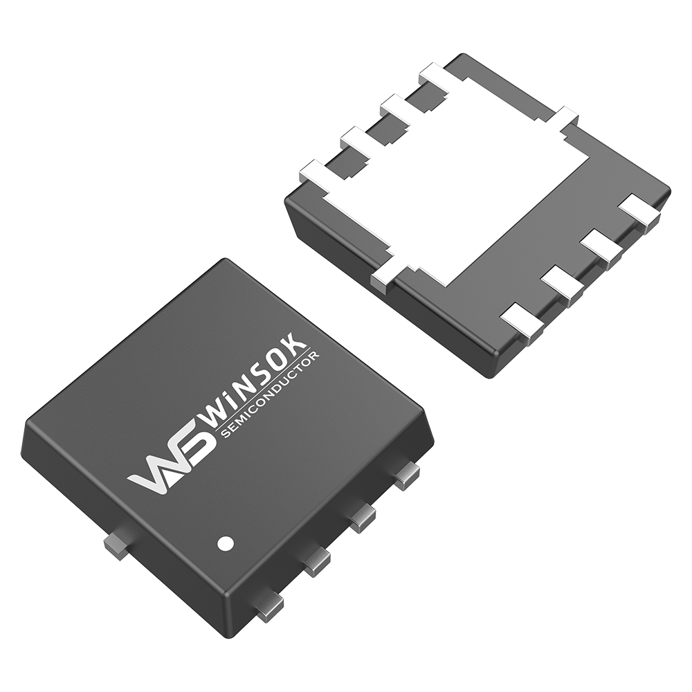
1, qualitative judgment MOSFET good or bad
MOSFET replacement principle and good or bad judgment, first use the multimeter R × 10kΩ block (built-in 9V or 15V battery), the negative pen (black) connected to the gate (G), the positive pen (red) connected to the source (S). When charging between the gate and source, the multimeter pointer will be slightly deflected. Again using the multimeter R × 1Ω block, the negative pen to the drain (D), the positive pen to the source (S), the multimeter indicates the value of a few ohms, indicating that the MOSFET good.
2, qualitative analysis of junction MOSFET electrode
The multimeter will be dialed to R × 100 file, the red pen to any one foot tube, black pen to another, so that the third foot is suspended. If you find a slight swing of the meter needle, prove that the third foot is the gate. If you want to get more obvious results, you can also use the body close to or with a finger to touch the suspended foot, as long as you see the needle deflected significantly, that is, indicating that the suspended foot for the gate, the remaining two feet for the source and drain, respectively.
Discriminatory reasons: JFET input resistance is greater than 100MΩ, and the transconductance is very high, when the gate is open-circuit, the space electromagnetic field can be easily induced by the gate voltage signal, so that the tube tends to cut off, or tends to conduction. If the human body directly to the gate induction voltage, due to the input interference signal is stronger, the above phenomenon will be more obvious. For example, the needle to the left bias is very large, it means that the tube tends to cut off, drain-source resistance RDS increases, drain-source current decreases IDS. on the contrary, the needle to the right side of the large deflection, that the tube tends to conduction, RDS ↓, IDS ↑. However, which direction the meter needle actually deflects should be determined by the polarity of the induced voltage (forward or reverse voltage) and the operating point of the tube.
Precautions:
The test results show that when both hands are insulated from the D and S poles and only the gate is touched, the meter needle is generally deflected to the left. However, when both hands touch the D and S poles respectively and the fingers touch the gate, the meter needle can be observed to deflect to the right. The reason for this is that several parts of the human body and resistance bias the MOSFET into the saturation region.
Crystal triode pin determination
Triode is composed of a core (two PN junctions), three electrodes and a tube shell, the three electrodes are called collector c, emitter e, base b. Currently, the common triode is a silicon planar tube, which is further divided into two categories: PNP-type and NPN-type. Germanium alloy tubes are now rare.
Here we will introduce a simple method of using a multimeter to measure the triode feet of the triode.
1, find the base pole, determine the tube type (NPN or PNP)
For PNP-type triode, C and E poles are the positive poles of the two PN junctions inside it, and the B pole is its common negative pole, while the NPN-type triode is the opposite, C and E poles are the negative poles of the two PN junctions, and the B pole is its common positive pole, and it is easy to determine the base pole and the type of the tube according to the characteristics of the PN junction's positive resistance is small, and the reverse resistance is large. The specific method is:
Use a multimeter dialed at R × 100 or R × 1K gear. Red pen touch a pin, and then use the black pen were connected to the other two pins, so that you can get three groups (each group of two) readings, when one of the two sets of readings are in the low resistance value of a few hundred ohms, if the public pins are the red pen, the contact is the base, the transistor's type of the PNP type; if the public pins are the black pen, the contact is the base, the transistor's type of the NPN type.
2, identify the emitter and collector
As the triode production, two P area or two N area within the doping concentration is different, if the right amplifier, the triode has a strong amplification, and vice versa, with the wrong amplifier, the amplifier amplification of a large number of very weak, so the triode with the right amplifier, the triode with the wrong amplifier, there will be a big difference.
After identifying the tube type and base b, the collector and emitter can be identified in the following way. Dial up the multimeter by pressing R x 1K. Pinch the base and the other pin together with both hands (be careful not to let the electrodes come into direct contact). In order to make the measurement phenomenon obvious, wet your fingers, pinch the red pen with the base, pinch the black pen with the other pin, and pay attention to the magnitude of the right swing of the multimeter pointer. Next, adjust the two pins, repeat the above measurement steps. Compare the amplitude of the needle swing in the two measurements and find out the part with larger swing. For PNP-type transistors, connect the black pen to the pin and the base pinch together, repeat the above experiments to find out where the needle swing amplitude is larger, for NPN-type, the black pen is connected to the base, the red pen is connected to the emitter. In the PNP type, the red pen is connected to the collector, the black pen is connected to the emitter.
The principle of this identification method is to use the battery in the multimeter, the voltage is added to the collector and emitter of the transistor, so that it has the ability to amplify. Hand pinch its base, collector, equal to the resistance through the hand to the triode plus a positive bias current, so that it conducts, at this time the magnitude of the meter needle swinging to the right reflects its amplification ability, so you can correctly determine the location of the emitter, collector.


