As a leading distributor of Winsok MOSFETs, we understand the critical role that gate resistors play in MOSFET performance and circuit reliability. This comprehensive guide will help you make informed decisions about gate resistor selection and implementation.
Understanding MOSFET Gate Resistors
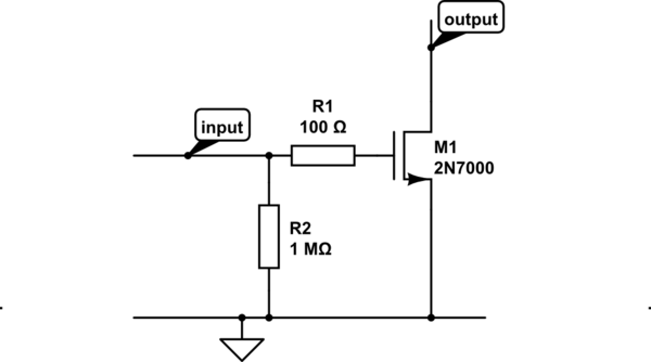
 MOSFET gate resistors are crucial components in power electronic circuits that play a vital role in controlling the switching behavior of MOSFETs. These resistors help manage the gate charge and discharge rates, ultimately affecting the device’s switching characteristics and overall circuit performance.
Key Functions of Gate Resistors
| Function | Description | Impact |
|---|---|---|
| Switching Speed Control | Manages the rate of gate voltage change | Affects turn-on and turn-off times |
| EMI Reduction | Minimizes electromagnetic interference | Improves circuit EMC compliance |
| Oscillation Prevention | Dampens unwanted oscillations | Enhances circuit stability |
| Current Limiting | Limits gate current peaks | Protects gate driver and MOSFET |
Selecting the Optimal Gate Resistor Value
The selection of an appropriate gate resistor value is critical for achieving optimal MOSFET performance. Several factors must be considered:
Key Selection Criteria:
- Switching frequency requirements
- Power dissipation capabilities
- Circuit parasitic elements
- EMI/EMC requirements
- Temperature considerations
Winsok MOSFETs: Superior Performance with Optimal Gate Resistance
At Winsok, we offer a comprehensive range of MOSFETs designed to work seamlessly with various gate resistor configurations. Our products feature:
- Advanced silicon technology for superior switching characteristics
- Optimized gate charge specifications
- Enhanced thermal performance
- Industry-leading reliability
Technical Considerations and Best Practices
[Previous HTML/CSS remains exactly the same...]
Technical Considerations and Best Practices
Gate Resistance Calculation
The optimal gate resistance (Rg) can be calculated using several key parameters. The following formula serves as a starting point:
Rg = Vdr / Ig(peak)
Where:
- Vdr = Gate driver voltage
- Ig(peak) = Peak gate current
Impact on Switching Parameters
| Parameter | Effect of Increasing Rg | Effect of Decreasing Rg |
|---|---|---|
| Turn-on Time | Increases | Decreases |
| Turn-off Time | Increases | Decreases |
| Switching Losses | Increases | Decreases |
| EMI Generation | Decreases | Increases |
Application-Specific Considerations
High-Frequency Applications
In high-frequency switching applications, the selection of gate resistance becomes particularly critical. Our Winsok high-frequency MOSFETs are optimized for:
- Switching frequencies up to 1MHz
- Minimal switching losses
- Superior thermal performance
- Excellent dv/dt immunity
Recommended Gate Resistance Values for Different Switching Frequencies
| Frequency Range | Recommended Rg Range | Notes |
|---|---|---|
| < 100 kHz | 10Ω – 47Ω | General purpose applications |
| 100 kHz – 500 kHz | 5Ω – 22Ω | Balance between switching speed and EMI |
| > 500 kHz | 2Ω – 10Ω | Optimized for high-frequency operation |
Power Supply Applications
For switch-mode power supply (SMPS) applications, gate resistance selection must consider:
- Input voltage range
- Output power requirements
- Efficiency targets
- EMC compliance standards
- Thermal constraints
Advanced Gate Drive Techniques
Separate Turn-on and Turn-off Resistors
Using different resistor values for turn-on and turn-off can optimize switching performance:
- Rg(on): Controls turn-on speed and dv/dt
- Rg(off): Manages turn-off characteristics
- Diode parallel to Rg(off): Enables faster turn-off
Winsok MOSFET Solutions
Our comprehensive range of MOSFETs includes:
| Series | Voltage Rating | Current Rating | Key Features |
|---|---|---|---|
| WS-HP Series | 30V-100V | Up to 100A | High Performance, Low RDS(on) |
| WS-UF Series | 60V-150V | Up to 75A | Ultra-Fast Switching |
| WS-RP Series | 200V-650V | Up to 50A | Rugged & Reliable |
Troubleshooting Common Issues
Gate Oscillation
If you encounter gate oscillation issues:
- Increase gate resistance value
- Check PCB layout for parasitic inductance
- Consider adding a small ferrite bead
- Verify gate driver compatibility
Excessive Switching Losses
To optimize switching losses:
- Evaluate gate resistance value
- Check gate drive voltage levels
- Optimize PCB layout
- Consider advanced gate drive techniques
Design Guidelines
PCB Layout Best Practices
- Minimize gate loop inductance
- Use dedicated gate return path
- Place gate resistor close to MOSFET
- Consider kelvin source connection
- Implement proper thermal management
Partner with Winsok
As your trusted MOSFET supplier, we offer:
- Technical support and design consultation
- Comprehensive documentation and application notes
- Sample programs for evaluation
- Reliable supply chain solutions
- Competitive pricing for volume orders
Why Choose Winsok?
- Industry-leading MOSFET technology
- Extensive product portfolio
- Expert technical support
- Reliable quality control
- Global distribution network
Conclusion
Proper selection and implementation of gate resistors are crucial for optimal MOSFET performance. Whether you’re designing a high-frequency power supply or a motor control system, Winsok offers the expertise and products you need to succeed. Contact our team today to discuss your specific requirements and find the perfect MOSFET solution for your application.


