
Creating an H-bridge using MOSFETs is a fundamental skill in electronics, especially for motor control applications. As a leading MOSFET supplier and authorized semiconductor distributor, we’ll walk you through the process of building an efficient H-bridge circuit using quality components.
What Makes MOSFET H-Bridges Special?
 H-bridges are essential circuits that enable bidirectional control of DC motors. While there are various ways to construct an H-bridge, MOSFETs offer several advantages:
- Higher efficiency with lower heat generation
- Fast switching capabilities
- Minimal voltage drop across the switches
- Suitable for high-current applications
Required Components
| Component | Quantity | Specifications |
|---|---|---|
| N-channel MOSFETs | 4 | WSF3036(A) or similar 30V/36A |
| Gate Drivers | 2 | Dual channel, bootstrap capable |
| Bypass Capacitors | 4 | 100nF ceramic |
| Bootstrap Capacitors | 2 | 100nF/50V |
Need high-quality MOSFETs for your H-bridge project?
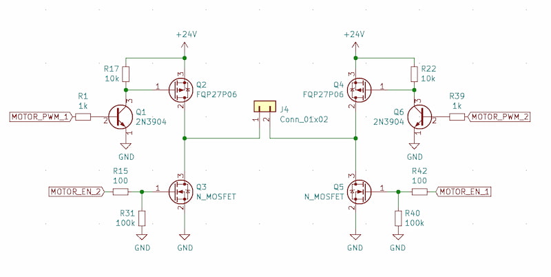
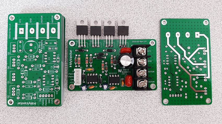
Step-by-Step H-Bridge Construction
1. Circuit Layout Planning
 The H-bridge layout is crucial for optimal performance. Position the MOSFETs in an H configuration with:
- High-side MOSFETs (Q1 & Q3) at the top
- Low-side MOSFETs (Q2 & Q4) at the bottom
- Motor connections between the pairs
- Keep gate driver traces short to minimize inductance
2. MOSFET Selection Guidelines
When selecting MOSFETs for your H-bridge, consider these crucial parameters:
VDS Rating:Should be at least 20% higher than your maximum supply voltage
Current Rating:Choose MOSFETs with ID rating 50% above your maximum motor current
RDS(on):Lower RDS(on) means better efficiency but higher cost
Gate Charge:Lower Qg enables faster switching frequencies
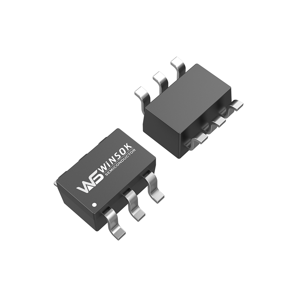
Recommended WINSOK MOSFETs for H-Bridge Applications
WSF3036(A)
- VDS: 30V
- ID: 36A
- RDS(on): 9.5mΩ
- Package: TO-252-2L
WSF40N06
- VDS: 60V
- ID: 50A
- RDS(on): 12mΩ
- Package: TO-252-2L
3. Gate Driver Implementation
Proper gate driving is essential for efficient MOSFET switching:
Key Considerations:
- Use dedicated gate driver ICs for reliable switching
- Implement bootstrap circuits for high-side MOSFETs
- Add gate resistors (10-100Ω) to control switching speed
- Include pull-down resistors (10kΩ) on gate inputs
4. Protection Mechanisms
Overcurrent Protection
Implement current sensing with shunt resistors and comparators
Thermal Protection
Add thermal sensors near MOSFETs
Dead-time Control
Ensure adequate dead-time (typically 1-2μs) between switching transitions
Flyback Diodes
Use fast recovery diodes or rely on MOSFET body diodes with proper rating
Common Issues and Solutions
Overheating MOSFETs
Causes:
- Insufficient heat sinking
- High switching losses
- Poor PCB thermal design
Solutions:
- Add proper heatsinks
- Optimize switching frequency
- Improve PCB thermal vias
Shoot-through Current
Causes:
- Insufficient dead-time
- Poor gate driver timing
- EMI issues
Solutions:
- Increase dead-time
- Improve layout
- Add snubber circuits
Need Professional Assistance?
 As an authorized MOSFET distributor, Olukey provides:
- Technical consultation for your H-bridge design
- High-quality WINSOK MOSFETs with guaranteed specifications
- Sample availability for testing and validation
- Volume pricing for production quantities


-

MOSFET gate source protection
-

N-Channel Depletion Mode MOSFET: Comprehensive ...
-
How to choose the right package MOSFET?
-

How MOSFETs work
-

CMS32L051SS24 MCU Cmsemicon® Package SSOP24 Bat...
-

Power MOSFET Package Types Guide
-

2N7002 LTspice Modeling and Simulation Guide
-

BJT vs MOSFET: Making the Right Choice for Your...
-

Understanding the Operation and Modeling of MOS...
-

Maximizing MOSFET Output Capacitance: Advanced ...
-

RDS(on) in MOSFETs: The Critical Parameter for ...
-

MOSFET Solid State Relays: Revolutionizing Mode...
-

EV dashboards are prone to break down, maybe it...
-

Original spot CMS79F726 package SOP20 touch but...
-

Building a MOSFET H-Bridge: Essential Guide for...
-
The difference between N-channel MOSFET and P-c...


